Hotline
 0859200531
Interface selection: Zener barriers or isolation interfaces
The decision between these two types of interface will normally be down to site preferences and both have advantages and disadvantages.
Zener barriers are much simpler than isolation interfaces and tend to be more flexible in application. Generally Zener barriers can be used in different circuits. Isolation interfaces tend to be designed for a specific application and are limited in the way they are used.
Earthing with Zener barriers is perceived to be difficult as they have a strict earthing requirement although in practice this rarely a problem. Maintaining an intrinsic safety earth is not as difficult as some believe but, particularly when only a few Zener barriers are used, it can introduce extra complication and cost.
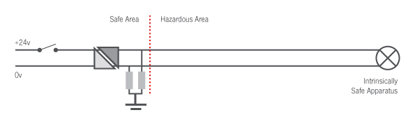
Isolation interfaces (also known as Galvanic Isolators) do not require the same degree of integrity on the Earth as Zener barrier interfaces. However to avoid the risk of cables charging to uncontrolled potentials and so acquiring stored capacitive energy which may be incendive, a discharge path to Earth should be provided. This would typically be between 200kΩ and 1MΩ and is not deemed to be earthing in terms of the instrumentation loop.
Selecting an intrinsic safety interface
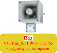
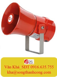
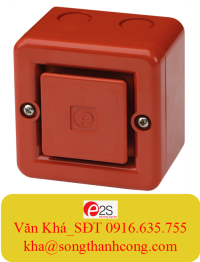
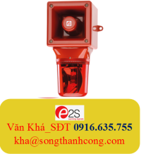
The associated apparatus (intrinsic safety interface) preserves the integrity of the field device such as E2S sounder or beacon. It can only do this if it limits the energy by way of voltage and current to a level below the maximum permitted by field device.
These values are the entity parameters (often referred to as safety parameters) and consist of voltage current power capacitance and inductance. All of these may not always be specified if they are irrelevant or can be derived directly from the other parameters.
The E2S sounders and beacons main terminals all have the same entity parameters (The suffix “i” denotes input characteristics)
Ui = 28v | Ii = 93mA | Pi = 660mW
This means that the integrity of the apparatus is maintained, i.e. it is safe, providing these figures are not exceeded. Therefore the associated apparatus (barrier) must have parameters of less than or equal to these figures.
Note that the power figure is not the direct calculation based on Voltage and Current; these are entity or safety parameters not actual working values.
The capacitance and inductance figures
Ci = 0µF | Li = 0mH
Refer to the capacitance or inductance that the apparatus contributes to the circuit. In the case of E2S sounders and beacons this is zero which simplifies the safety assessment of the circuit.
A suitable barrier would have entity parameters of
Uo ≤ 28v | I o ≤ 93mA | P o ≤ 660mW
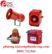
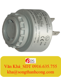
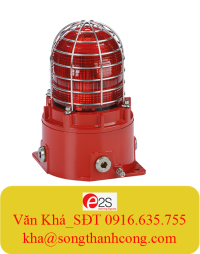
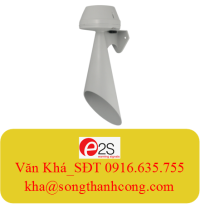
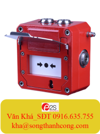
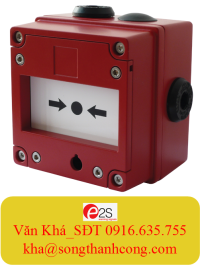
E2S offers a range of intrinsically safe sounders, beacons and manual call points which can be viewed here.