 Mr Vuong
Hiệu quả của tín hiệu thị giác
Ngoại trừ có thể có các chỉ báo trạng thái, mục đích của dải tín hiệu hình ảnh E2S là thu hút sự chú ý so với đèn chiếu sáng hoặc đèn mục đích chung nhằm chiếu sáng một khu vực nhất định và không nhất thiết phải thu hút sự chú ý. Do đó, hiệu quả hoặc cường độ ánh sáng của một thiết bị trái ngược với khả năng chiếu sáng của nó có lẽ là điều cần cân nhắc quan trọng. Các nguồn sáng khác nhau có thể cung cấp cường độ ánh sáng hiệu quả khác nhau và khả năng thu hút sự chú ý, đặc biệt là khi nhấp nháy; tuy nhiên, ngược lại khả năng chiếu sáng của một khu vực nhất định có thể khá kém.
E2S cung cấp thông tin liên quan đến hiệu quả của tín hiệu thị giác dựa trên các phép đo thực tế cho từng kiểu máy trong phạm vi E2S. Thông tin được cung cấp KHÔNG phải dựa trên quy tắc giả định và / hoặc tính toán đơn thuần. Do đó, chúng tôi tin tưởng rằng các giá trị đầu ra ánh sáng đo được của chúng tôi có ý nghĩa và sẽ hỗ trợ tốt hơn cho việc lựa chọn sản phẩm.
Có một sự lựa chọn của các nguồn phát sáng,
- Bóng đèn sợi đốt / dây tóc – usually operated in conjunction with an additional circuit, both a steady output and more effective blinking output may be achieved. The filament light bulb gives adequate performance, at a relatively low cost, which may be enhanced with a freznel lens. It does however have quite a short life, and is further shortened when exposed to quite low levels of vibration.
- Bóng đèn Halogen – the filament of this bulb is enclosed in halogen gas and glows at a slightly higher temperature than a regular bulb. a more efficient light output and longer bulb life of up to three times that of a regular bulb. If a 40w bulb is considered, a halogen version may be expected to produce an increase of up to 80% in Luminous Efficiency (lumen per watts) when compared with a regular bulb.
- Bóng đèn Xenon (strobe) – operating at high voltage generated by an inverter circuit, the xenon tube is ignited creating an instantaneous brilliant flash of light, which may further be enhanced when viewed through a freznel lens. The energy of the flash is a function of the tube size, the voltage across it and the capacitor discharging into it. The tube life is typically 5 to 8 million flashes with after which erosion of light output is experienced until the tube eventually fails.
- L.E.D (light Emitting Diode) – a semiconductor device, which unlike the filament bulb and the xenon tube emits only one frequency of light (i.e. one colour) dependent on its construction. L.E.D technology is developing and does not as yet offer as bright a solution as the xenon tube, it does however offer an extremely low current and very long life time, giving an effective solution where an indication or status is required.
Làm thế nào để E2S đo hiệu năng ánh sáng (Candela - cd) của Tín hiệu Trực quan?
A spectrometer is used for measuring the average effective luminous intensity of an entire beacon lens. This is then translated into an Effective Candela figure (cd).
In the case of a flashing beacon such as a xenon strobe the pulse duration as measured between the 10 % of peak amplitude for the leading and trailing edges of the pulse is measured. Light levels are collected during the pulse period, these are translated using the Blondel-Rey formula into an Effective Candela figure (cd). This is the intensity that would appear to an observer if the light were burning steadily.
The effective luminous intensity (Ieff), expressed in candela (cd), is calculated for each pulse measured using the following Blondel-Rey formula:
.png)
Where,
I(t) is the instantaneous value in candela (cd);
a = visual time constant where either 0.2 (nighttime) or 0.1 (daytime) constants are used in calculation.
t2 – t1 is the light pulse duration as measured between the 10 % of peak amplitude for the leading and trailing edges of the pulse.
Measured Effectiveness compared with Rule of thumb / calculated-only Effectiveness – Xenon Strobe Beacons
When evaluating or comparing output data of more than one visual signalling device, it is probably worth considering how the data has been established.
Rules of thumb and calculations based on the energy of the flash tube within a xenon strobe beacon have customarily been used to give an indication of effectiveness. However when comparing outputs derived by calculations based on energy alone, to measured outputs with a spectrometer or similar, the output is often overstated in terms of effective candela (candle power) and especially in terms of peak candle power. This can all too often be misleading and unless two devices have been measured for output then their effectiveness in terms of candela output cannot be accurately compared.
E2S state two measures of effective light output for all xenon strobe beacons both of which have been carried out and subjected to, a fully assembled, product fitted with a clear lens, these are,
Effective Candela (cd) – Measured: also known as effective candle power, this is the measured intensity that would appear to an observer if / when the light was burning steadily. This data which should be used when comparing two different visual signalling devices.
Peak Candela (cd) – Measured: also known as peak candle power, this is the maximum intensity measured generated by a flashing device during its light pulse. – it is recommended the peak candela figure should not be used when comparing two different visual signals.
In the case of xenon strobe visual signals E2S state calculated figures based on the energy rating of the flash tube, this type of information has customarily been used within the visual signalling industry to give a rule of thumb indication and is subject to many anomalies that give rise to inaccurate and overstated output figures. This may be due to differences in size and efficiency of lens, physical shape of the strobe lamp and arrangement relative to the lens and the efficiency of the strobe flash tube itself. Other factors, not least lens color influence light output and is dealt with later.
Below is a description of the calculated light output figures included for information only. The difference between these figures and actual measured outputs is demonstrated later.
Effective Candela (cd) – Calculated: also known as effective candle power, typically assumes 1 Joule of energy supplied to a flash tube assimilates 50 cd (candela)
Peak Candela (cd) – Calculated: also known as peak candle power, typically assumes 1 Joule of energy supplied to a flash tube assimilates 100,000 cd (candela) – it is recommended the peak candela figure should not be used when comparing two different visual signals.
An Example of Differences between Measured and Calculated Effective Candela data.
As stated before when comparing two visual signalling devices their measured effective candela should be compared as opposed to calculated effective candela. Peak candela should not be used for comparison purposes with respect to effectiveness.
The visual signals below are all 5 Joule energy rated xenon strobe beacons. They are physically different both in terms of enclosure and lens arrangement. Table 2, demonstrates the anomalies and assumptions which lead to inaccuracies if the effective candela is calculated and / or a rule of thumb is applied as opposed to being measured
Table 1: Comparison of Measured effective candela with Calculated effective candela: Three different 5 Joule E2S beacons.
|
5 Joule Visual Signal
|
MEASURED Effective Candela (cd) ; |
Warning Distance |
|
L101 |
200 |
22m / 73ft |
|
B300STR |
125 |
18m / 58ft |
|
BExBG05D |
105 |
16m / 53ft |
|
CALCULATED Effective Candela (cd) |
Warning Distance |
|
|
L101 |
250 |
112m / 366ft |
|
B300STR |
250 |
112m / 366ft |
|
BExBG05D |
250 |
112m / 366ft |
Beacon effectiveness & range
A common question as far as visual signalling is concerned is the range of a given device. The effective candela (or effective candle power) of a device may be used to determine the effective range using the following formula also referred to in EN54-23, and IES (Illuminating Engineering Society of North America (IES) Lighting Handbook, Fifth Edition);
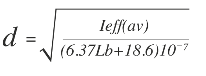
The formula below may be used to convert effective candela into effective warning distance, in other words, alert rather than inform.
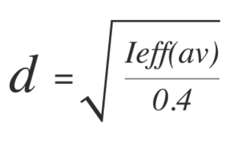
WhereIeff(av) = Effective Candela
d = Distance (m)
The formula below may be used to convert effective candela into viewing distance or range, based on normal visibility in day time conditions.
WhereIeff(av) = Effective Candela
d = Distance (feet)
Lb = Foot-Lamberts background illuminance (normal day time conditions, Lb = 2919 ft-L)
From the above two formulas the table below gives an indication of both warning distance and range of a visual signal given an effective candela measurement.
Table 2: Indication of warning distance and range of a visual signal given an effective candela measurement.
|
Effective Candela cd |
Warning Distance m |
Warning Distance ft |
Viewing Distance m |
Viewing Distance ft |
| 5 | 3.54 | 11.61 | 16 | 52 |
| 10 | 5.00 | 16.40 | 22 | 73 |
| 25 | 7.90 | 25.92 | 35 | 116 |
| 50 | 11.18 | 36.68 | 50 | 164 |
| 100 | 15.81 | 51.87 | 71 | 232 |
| 150 | 19.36 | 63.52 | 87 | 284 |
| 200 | 22.36 | 73.36 | 100 | 328 |
| 250 | 25.00 | 82.02 | 112 | 366 |
| 300 | 27.39 | 89.86 | 122 | 401 |
| 350 | 29.58 | 97.05 | 132 | 434 |
| 400 | 31.62 | 103.74 | 141 | 464 |
| 450 | 33.54 | 110.04 | 150 | 492 |
| 500 | 35.35 | 115.98 | 158 | 518 |
| 550 | 37.08 | 121.65 | 166 | 544 |
| 600 | 38.72 | 127.03 | 173 | 568 |
How much does lens colour effect the intensity of a light source?
The effect of lens colour on the intensity of the light source within an industrial environment may be expressed as follows:
| Clear | Yellow | Amber | Red | Blue | Green |
| 100% | 93% | 70% | 23% | 24% | 25% |
Siting of a visual signalling device
Omni-directional light dispersion should be the first consideration when installing a beacon, ensuring free air movement around the beacon enclosure and therefore preventing the build up of heat from the light source emitted during the normal operation of the beacon. Vibration should be avoided particularly with filament bulb beacons. Light travels in straight lines, the beacon will be far more effective if positioned in the line of sight rather than relying on reflections. Where applicable audible signals should always be the primary warning with the beacon used as a secondary indication or status.
IEC 73 colours
- RED – Danger Act Now.
Danger of live or unguarded moving machinery or essential equipment in
protected area.
- AMBER – Warning, Proceed with Care.
Temperature or pressure different from normal level.
- GREEN – Safety Precaution: Go Ahead
Checks complete, machine about to start.
- BLUE – Site Specified.
Pre-set ready or remote control.
- CLEAR – No specific Meaning.
Could confirm an earlier message.
Choose your application below to view suitable visual signals: