 Mr Vuong
Isolation interfaces: Intrinsic safety solutions
These are typical system diagrams using isolation interfaces for E2S intrinsically safe sounders and beacons. The following circuits are for are for illustration only, installation and details may be omitted for clarity.
Please refer to the relevant certification prior to use. As all E2S sounder and beacons have the same entity parameters in most circuits different E2S intrinsically safe field apparatus may be used providing it has the relevant input feature. Where examples show the IS-mini range a direct replacement can be made using the IS-A105N and IS-L101L or combination.
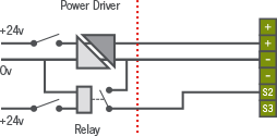
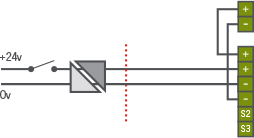
The simplest installation is with a Single stage alarm with a single channel isolation interface (Power driver). This is suitable for all E2S Intrinsically safe sounders and beacons.
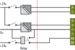
When using isolation interfaces the integrity of the isolation must be maintained so an intrinsically safe relay is used to switch the second stage alarm.
Although the relay contacts can be treated as simple apparatus, the relay must be certified. (see list of suggested relays)
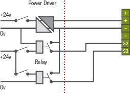
Similarly add another relay (or a double relay module) for the 3rd stage audible alarm.
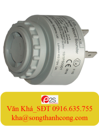
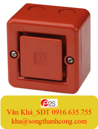
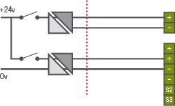
The sounder and beacon IS-mC1 or the combination of IS-A105N and IS-L101L can be powered with a single channel interface.
For independent control use a double channel, or 2 separate isolation interfaces.
Again adding a relay gives 2nd level alarm option.
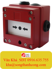
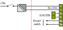
The combined IS-A105N / IS-L101L has a mute option, adding a switch will mute the alarm.
Depending on the DIP switch settings on the IS-L101 reset occurs:
On alarm condition being removed i.e. power down of IS-L101L or after a dip switch selectable interval – from 5 seconds to 2 hours.
Note the reset switch does not need to be certified as it is considered to be simple apparatus.
Should you manufacture a suitable Intrinsically safe interface or wish to comment on these applications please contact us.
| EN1127-1 | Explosive atmospheres: Explosion prevention and protection | |
| Part 1: | Basic concepts and methodology |
| EN 60079 | ELECTRICAL APPARATUS FOR EXPLOSIVE GAS ATMOSPHERES | |
| Part 0 | General requirements | |
| Part 14 | Installation (and selection) of equipment in hazardous areas | |
| Part 25 | Intrinsically safe systems |
Suggested reference book on intrinsic safety and hazardous areas Electrical Apparatus and Hazardous Areas by Robin Garside. 5th Edition 2007 ISBN 978-0-9516848-4-9